The fundamental standard for rotary lawn mower cut quality requires the front blade tips to sit exactly 1/8 inch to 1/4 inch (0.125" to 0.250") lower than the rear blade tips. When forward pitch rake falls within this aerodynamic tolerance band, spinning blades slice grass stems cleanly once and immediately discharge or mulch the clippings through the chamber without parasitic rear re-cutting.
The Aerodynamics of Rotary Mower Deck Pitch
Mower deck leveling is commonly misunderstood as requiring a completely flat, parallel plane across all four corners. In reality, a parallel deck compromises mower efficiency. Rotary mower blades rotate at tip speeds exceeding 16,000 to 19,000 feet per minute (FPM), creating a high-velocity cyclonic vacuum inside the baffled housing.
If the rear of the cutting chamber is adjusted to the same height as the front, clippings drawn into the rear chamber vortex are struck a second time by the descending rear blade wing. This secondary collision absorbs up to 2.5 to 4.0 horsepower from the engine, forces grass juice onto the deck underside, and mashes severed stems rather than ejecting them cleanly.
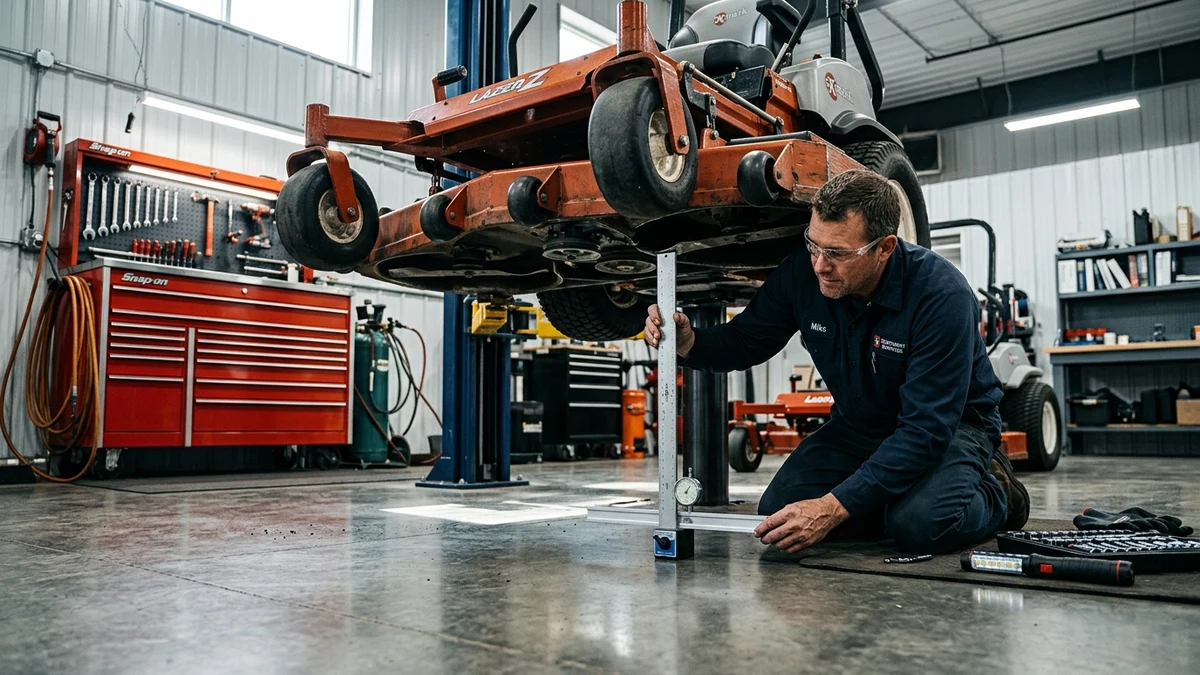
Step-by-Step Deck Leveling Protocol
Before making physical adjustments to deck lift linkages, technicians must complete three preliminary checks to eliminate false measurement readings:
- Tire Pressure Calibration: Uneven tire pressure is responsible for over 60% of reported uneven cuts. Inflate drive tires to exactly 12 to 14 PSI and front caster tires to 14 to 15 PSI (consult frame label for specific PSI). A 2 PSI difference creates a 1/4-inch lateral slope.
- Hard Surface Staging: Position mower on level concrete. Never attempt deck leveling on turf, asphalt driveways, or gravel pads, which introduce lateral deflection.
- Blade Straightness Verification: Rotate each blade tip to a central fixed pointer. If one blade tip drops more than 0.10 inches lower than its opposing wing, replace the bent blade before adjusting deck chains or trunnions.
Pitch & Rake Diagnostic Reference Table
| Pitch Condition | Rake Measurement (Rear − Front) | Cut Quality Symptoms | Corrective Action |
|---|---|---|---|
| Optimal Forward Rake | 0.125" – 0.250" (+1/8" to +1/4") | Clean discharge, crisp tip shearing, no clipping buildup, smooth engine sound | None; lock jam nuts against clevis |
| Dead Level (Zero Rake) | 0.000" (0/8") | Rear blade double-cutting, ragged browning leaf tips, heavy engine load in dense turf | Lengthen front draft rod or raise rear hangers 1 to 2 turns |
| Reverse Negative Rake | < 0.000" (Rear Lower than Front) | Severe engine bogging, grass clump drop-out, washboard striping, deck clogging | Raise rear lift chains immediately by 2 to 4 turns clockwise |
| Excessive Forward Rake | > 0.375" (> +3/8") | Turf scalping on hill crowns, stepped uneven rows, reduced suction discharge | Lower rear hangers or tighten front draft link |
Lateral Side-to-Side Balancing
While forward rake controls aerodynamic evacuation and power consumption, side-to-side balance dictates cut flatness across the mowing swath. Position the outer blade tips perpendicular to the frame (pointing straight out left and right). Measure from concrete to cutting edge on both sides.
If the left-to-right variance exceeds 1/8 inch (0.125"), loosen the lock nut on the lower side's lift linkage trunnion and turn clockwise to raise the low side. Always re-measure both sides after tightening lock nuts, as tightening the jam nut can alter final clearance by up to 0.040 inches.